


Please Leave Us A Message
Privacy statement: Your privacy is very important to Us. Our company promises not to disclose your personal information to any external company with out your explicit permission.
 April 02, 2022
Faced with the reality that the earth's ecological environment is deteriorating and resources are increasingly scarce, governments around the world have adopted many policies and measures to support and develop energy-saving and environmental protection industries. Solar LED street lamps are a comprehensive application of solar energy development and energy-saving technologies in the field of lighting. According to statistics, lighting consumption accounts for about 20% of the total electricity consumption. Reducing lighting power is an important way to save energy. Solar energy is clean, environmentally friendly and renewable, and LED lighting is currently the most in the world. Advanced lighting technology is the fourth generation light source after incandescent lamp, fluorescent lamp and high-intensity gas discharge lamp. It has simple structure, high efficiency, light weight, good safety performance, no pollution, maintenance-free and long life, controllable performance. Strong features are considered to be the best way to achieve energy saving in the field of lighting. There are statistics showing that only Led Street Lights can save energy for China by saving about one dam from the Three Gorges Dam every year. Due to the energy saving and environmental advantages of LED lighting fixtures, its global output has increased in recent years.
The solar Led Street Lamp controller designed in this paper firstly detects the solar cell output and battery power and other parameters to determine the system working state, and uses the maximum power point tracking MPPT algorithm to achieve maximum energy collection. After the energy storage is completed, the PWM technology is utilized. Adjusting the brightness of the LED to further save energy, thus realizing the automatic control and intelligent energy management of the whole system, and is more conducive to the application and promotion of solar street lamps.
1 Introduction to Solar LED Street Light System
1. 1 The composition of the solar Led Street Light system
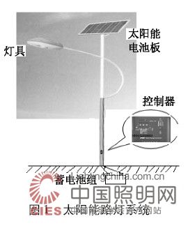
The Solar Street Light system consists of the following parts: solar panels, LED lamps (including LED light source, pole and lamp housing), controller, battery pack, as shown in Figure 1.
1. 2 Basic Principles of Solar LED Street Light System
The Solar Panel made by the photovoltaic effect principle receives solar radiation energy and converts it into electric energy output during the day, and is stored in the battery through the charge and discharge controller; when the illumination is gradually reduced at night, the charge and discharge controller detects this change, and the battery starts. Discharge the LED street light. After the battery is discharged for about 10 hours, the charge and discharge controller operates and the battery discharge ends.
According to the sunshine characteristics of Hainan Sanya and the design standards of urban road lighting [5], the components of the system are as follows: LED street light 1 group (32 W, 24 V, 1.4 A; LED 1 W light source; 4 groups in parallel, each group 8 series); 2 solar panels (each group rated output voltage 18 V, operating current is 5. 6 A, open circuit voltage is 21. 2 V, short circuit current is 6. 1 A, peak power is 80 W); Battery (12 V, 200 Ah; overcharge voltage 14.8 V, float voltage 12.3 V, over discharge voltage 10. 8 V).

2 Hardware Design
Although the solar LED street light controller is the least valuable part of the overall system, it is the core control part of the entire system. A well-designed controller, in addition to the most basic charge and discharge control functions, can also control the solar cell array to absorb solar energy as much as possible to improve efficiency; prevent battery overcharge and deep discharge, and extend battery life; Environment, adjust the brightness of the LED light source, especially in the latter half of the night to achieve half-power lighting load, so as to save energy as much as possible. Due to the large uncertainty of the output power of the photovoltaic panel, the charge and discharge characteristics of the battery are nonlinear. The other two are greatly affected by the environment, so designing a good performance charge and discharge controller has a great impact on system performance. This paper is a useful exploration of controller design.
The controller designed in this paper uses STC12C5410AD MCU as the main control device. The device has 4 PWM channels, 8 10-bit ADC channels, and the operating frequency is up to 35 MHz. The instruction is compatible with 51 MCU but the speed is 8~12 times faster. Design requirements. Since the two sets of solar cells are connected in series, the output voltage is 36 V, the battery voltage is 12 V, and the LED Street Lamp is 24 V. Therefore, the charging circuit uses a DC/DC buck converter circuit (Buck), and the discharge circuit is used. The DC/DC boost converter circuit (Boost) implements the charge and discharge control strategy through software, which ultimately achieves the goal of improving efficiency and energy saving (as shown in Figure 2). This paper focuses on the charge and discharge circuit and its control strategy.
2. 1 charging circuit and control strategy
The charging circuit consists of inductor L1, power MOSFET T1 and freewheeling diode D2 to form a buck Buck circuit, as shown in Figure 3. By changing the pulse width (Pulse Width Modulation, PWM) applied to the MOSFET control gate The output voltage of the solar panel can be changed. By detecting the output voltage and current of the solar panel, the voltage and current of the battery, determining the state of charge of the battery, selecting a suitable charging mode to optimize charging of the battery. When the battery voltage exceeds a certain voltage, Turn off T1 to prevent the battery from overcharging. When the system detects that the ambient light is sufficient, the controller will enter the charging mode.

However, the efficiency of charging is closely related to the characteristics of charging power source (solar battery), load (battery) and environment. The output power of solar cell is a nonlinear function of sunshine intensity and ambient temperature [1], as shown in Figure 4. That is to say, when the sunshine intensity is increased, the maximum output power increases accordingly; when the temperature increases, the output power decreases; but under certain conditions, there is always a maximum output power point. When the temperature effect is ignored, different illumination conditions The intersection of the output characteristic and the load curve L, A, B, C, D, E (operating point) is obviously not the maximum power point. If direct matching is used, the output power loss is inevitable.

Using the maximum power point tracking MPPT (Maximum Power Point Track) control strategy, the collected solar energy can be converted into electrical energy as much as possible and stored in the battery pack. The MPPT control strategy mainly includes interference observation method, admittance increase method and fixed parameters. Algorithms such as law. Here the interference observation method [1] is used. The idea is that the controller changes the output voltage or current of the photovoltaic cell with a small step size in each control cycle—“interference”, and the direction of change can be increased or Decrease; compare the output power of the photovoltaic cell before and after, if the output power increases, continue the interference process according to the direction of the previous cycle; if the output power decreases, change the direction of the interference, and finally reach the stable at the maximum power point. It is also possible to reduce the step size to further approach the maximum power point.
In addition, lead-acid batteries are the most economical and practical power storage devices under current conditions. The capacity and life of lead-acid batteries are important parameters of batteries, which are greatly affected by the charging method. The acceptable ideal charging curve is that the charging current is pressed with time. The exponential decay curve [3], but the polarization phenomenon restricts the battery life and the charging mode of the photovoltaic cell power generation system. Therefore, it is necessary to adopt a phased charging strategy according to the battery charging characteristic curve to improve the charging efficiency and extend the charging efficiency. Battery life. The battery charging strategy here is three-stage charging (fast charge, over charge and float charge).
(1) The output mode of the charging circuit in the fast charging phase is equivalent to the current source. The output current of the current source is determined according to the maximum acceptable current of the battery. During the charging process, the battery terminal voltage is detected, and when the battery terminal voltage rises to the switching threshold After that, the charging circuit goes to the overcharge phase. The output current is fixed and the output voltage is controlled by the MPPT algorithm.
(2) The charging circuit provides a higher voltage to the battery and detects the charging current. When the charging current drops below the switching threshold, the battery is considered to be fully charged and the charging circuit is switched to the floating charging phase.
(3) After the battery pack is fully charged in the floating charge phase, the best way to maintain the charge is to provide the battery with a precise, temperature-compensated float voltage.
2. 2 discharge circuit and control strategy
The load of the discharge circuit is a high-power LED street light, which is a green light source connected by a high-brightness LED of 1 W and above according to a certain topology. The luminous intensity of the high-power LED Street Lamp is proportional to the current flowing. The current and voltage parameters of the power LED have typical PN junction volt-ampere characteristics, and small changes in forward voltage drop cause large forward current changes. Unstable operating current affects LED life and light decay, so high power The LED drive circuit must provide a constant current [2 - 3]. Its control circuit mainly uses DC / DC boost drive circuit ( Boost), the control strategy uses pulse width modulation (PWM), and the Boost charging circuit is shown in Figure 5.

Inductor L2, power MOSFET Q2 and D3 form a step-up DC/DC converter. The output PWM2 is controlled by a single-chip microcomputer to obtain a stable output voltage. The constant current control of the two LEDs is controlled by PWM3 and PWM4 channels. These two loads can also be used as half-power point control; R7 and R10 provide current feedback sampling of the LED illumination driver circuit; other time control functions, temperature compensation circuits and battery over-discharge protection circuits are not discussed in detail here.
3 software design
The software design mainly assists the hardware circuit to complete the control strategy of the controller. It consists of the main program and subroutines such as charging and discharging, as shown in Figures 6 to 9. The charging subroutine completes the three-stage charging conversion according to the voltage and current of the battery. The MPPT algorithm is used in the fast charge phase to maximize the output power of the photovoltaic cell. The electronic program adjusts the load current through PWM technology, and the load can be completely cut off in the middle of the night to achieve a half-power lighting load.


4 Conclusion
Solar LED street lighting system is the perfect combination of solar energy development and utilization of a new generation of green light source LED. After many times of comprehensive debugging of software and hardware, this article uses STC12C5410AD single-chip microcomputer as the core design of the intelligent controller, which realizes the three-stage charging control function as a whole. It can effectively prevent the battery from overcharging; at the same time, it can realize the timing and half power point to cut off the load. When the battery voltage is lower than the overdischarge voltage, the load will also be cut off, thus the battery over discharge protection. The system has energy utilization and work reliability. Certain practical value, considering that the wind resources in Sanya are also rich, the next research direction will be to make full use of the complementarity of solar energy and wind energy to ensure uninterrupted lighting throughout the year, thus achieving zero pollution and zero emissions. The green lighting system takes it a step further.
The above is the Design of Solar LED Street Light Controller Based on STC Microcontroller we have listed for you. You can submit the following form to obtain more industry information we provide for you.
You can visit our website or contact us, and we will provide the latest consultation and solutions
Send Inquiry
Most Popular
lastest New
Send Inquiry
Privacy statement: Your privacy is very important to Us. Our company promises not to disclose your personal information to any external company with out your explicit permission.
Fill in more information so that we can get in touch with you faster
Privacy statement: Your privacy is very important to Us. Our company promises not to disclose your personal information to any external company with out your explicit permission.