


Please Leave Us A Message
Privacy statement: Your privacy is very important to Us. Our company promises not to disclose your personal information to any external company with out your explicit permission.
 April 12, 2022
The solar LED Street Light scheme introduced in this article can automatically detect the ambient light to control the working status of the street light, the maximum power point tracking (MPPT) guarantees the maximum Solar Panel efficiency, the constant current control LED, and with the battery status output and the user can set LED working time and other functions.
System structure and implementation principle
At present, commonly used street lights are high-voltage sodium lamp structures powered by commercial power. The electronic driving parts of high-pressure sodium lamps need to convert the commercial power from AC to DC and then reverse to AC to drive, resulting in lower system efficiency; and because of the use of Mains power requires the laying of complex and expensive pipelines. Solar-Led Street Light does not have the above problems, because the solar panel output is DC power, and LED is a DC-driven light source, the combination of the two can improve the efficiency of the entire system; the use of solar energy also eliminates the laying of cables and The cost of its related projects.

Figure 1 is a schematic diagram of a solar-LED street light. When the solar panel is exposed to sunlight, its internal PN junction will form a new electron-hole pair, and a direct current can be generated in a loop; this current flows into the controller and will charge the battery in some way. The battery will be charged during the day and will provide energy to the LED at night. The work of the LED is performed through the controller. The controller will also monitor the status of the LED and control the duration of the work while ensuring the constant current of the LED. In the case of continuous rainy days and insufficient battery power, the controller will send a control signal to start the external mains power supply system (not included in the controller) to ensure the normal operation of the LED. The external mains power supply system is only used as a back-up energy source. It is used only when the battery power is insufficient. The battery is fully charged only by solar energy to ensure maximum use of solar energy.
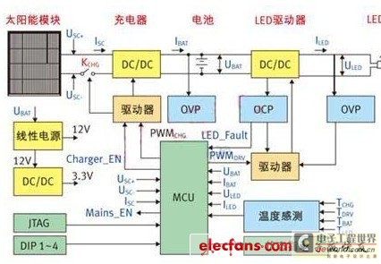
FIG. 2 is a structural block diagram of a controller. After the solar panel comes in, it will first connect to the DC/DC converter (battery charging circuit) through a switch MOS transistor KCHG. The output of this converter is connected to both ends of the battery (the actual circuit will be connected to the battery via a fuse first). ). In addition, KCHG has two functions: one is to prevent the anti-charging current coming from the battery when the output of the solar battery is low; and the other is to protect the circuit when the polarity of the solar battery is reversed. DC/DC converters use buck topology. The choice of topology must not only consider the maximum power point voltage of the solar panel and the maximum voltage of the battery, but also take into account both efficiency and cost. Between the battery and the LED is also through a DC / DC converter (LED driver circuit), the LED should use a constant current control mode, taking into account the battery voltage fluctuation range and the LED operating voltage range, the design circuit uses a flyback topology Structure to ensure constant current output. The efficiency of the flyback topology is generally not as high as a simple step-up or step-down circuit. If you want to increase the efficiency of the system, you can use a step-up or step-down circuit by optimizing the relationship between the battery voltage and the LED voltage to increase the efficiency and possibly reduce further. cost.
The control of the entire controller is achieved through an MCU. The main tasks of the MCU include the following: First, the use of MPPT algorithm to optimize the efficiency of solar panels; Second, the appropriate charging mode for different battery states; The third is to ensure that the LED The constant current output of the drive circuit; fourth is to judge the day and night and use this to switch the battery charge and discharge modes; the last is to provide monitoring protection, temperature monitoring, status output and user control input detection (DIP1 ~ 4) and other functions. The most important choice of the MCU is to meet the needs of the ADC, GPIO, and external interrupts. It is not necessary to simply pursue speed. Table 1 lists the use of MCU peripherals in actual circuits. Taking into account the need for future expansion, the main control chip uses STM32F101RXT6 (STMicroelectronics' latest STM32 series MCUs, using the Cortex-M3 core).

Table 1: MCU Peripheral Allocations.
The auxiliary power supply of the controller is directly converted from the battery. The battery input is 12V through the linear power supply (L78L12), and the logic circuit and the PWM switch signal are amplified. The 3.3V is connected to the switching power supply (L5970D) through 12V, mainly for the MCU and peripheral circuits. Power supply, the reason why switching power supply is used in order to improve conversion efficiency (reducing battery power consumption) and can provide enough load in the future expansion of the system, of course, in order to reduce costs, can be achieved with a linear power supply.
The main function of the controller
The main functions of the controller include two aspects: battery charging and battery supply to the LED.
Battery charging
When the system detects that the ambient light is sufficient, the controller enters charging mode. There are two more important voltage values for battery charging: deep discharge voltage and float charge voltage. The former represents the state in which the battery is used up under normal conditions of use, while the latter represents the maximum voltage limit for battery charging. These parameters should be found in the battery product manual. In the design circuit for the 12V battery, set the deep discharge voltage to 11V and the float charge voltage to 13.8V (all at the room temperature voltage value, the two values in the software increase the corresponding temperature compensation), the specific charge The pattern is shown in Table 2.
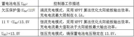
It can be seen from Table 2 that the MPPT algorithm is used for the trickle charge mode and the constant current charge mode. There are many ways to implement the MPPT algorithm. There are many papers in the industry to discuss this, in general there are advantages. In contrast, relatively simple perturbation observations are used in designing circuits (Perturbance and Observation). The basic idea of this control method is to determine whether the next step is to increase or decrease the duty cycle by increasing or decreasing the duty cycle of the charge circuit switching signal PWMCHG and then observing whether the output power is larger or smaller. As the output of solar panels changes relatively slowly and is a single pole, this method can still receive better results.
2. Battery discharge
When the system detects insufficient ambient light, it enters the battery to power the LED. The LED current is sampled and sent back to the MCU through the high current detection chip (TSC101AILT), and the MCU obtains a constant output current by adjusting the duty cycle of the switching signal PWMDRV. In order to achieve the purpose of energy saving, the constant current value of the LED will be adjusted according to the ambient light intensity detected by the system: when the ambient light changes from bright to dark, the output current of the system will also be correspondingly small; when the ambient light is completely dark, The output current of the system also reaches the preset maximum value. In addition to the ambient light control LED output, the user can also set the time switch control function by setting the state of the switch DIP1~4. The system will control the LED from bright 5 minutes to 12 hours according to the setting combination of DIP1~4.
In addition, in order to improve the reliability of the system, a series of hardware and software protection functions such as solar panels, batteries, and LEDs have been added to the design circuit. Based on this system platform, the performance of the system can be further optimized by adding smart light-emitting diodes, adding communication modules, and adopting wind-solar hybrid systems.
This article concludes
The street light system has been successfully implemented at the entrance of the STMicroelectronics Building. All street light systems have been operating for six months and their working conditions are normal.
The above is the Solar LED street light solution we have listed for you. You can submit the following form to obtain more industry information we provide for you.
You can visit our website or contact us, and we will provide the latest consultation and solutions
Send Inquiry
Most Popular
lastest New
Send Inquiry
Privacy statement: Your privacy is very important to Us. Our company promises not to disclose your personal information to any external company with out your explicit permission.
Fill in more information so that we can get in touch with you faster
Privacy statement: Your privacy is very important to Us. Our company promises not to disclose your personal information to any external company with out your explicit permission.