


Please Leave Us A Message
Privacy statement: Your privacy is very important to Us. Our company promises not to disclose your personal information to any external company with out your explicit permission.
 April 04, 2022
With the declining fossil energy sources and the excessive emissions of greenhouse gases, global warming has become more and more important. On the one hand, people are actively developing various types of renewable new energy, on the other hand, they are also advocating green energy conservation and emission reduction. Environmental technology. As an inexhaustible source of clean energy, solar energy has become an important representative of many renewable energy sources. In the field of lighting, long-life, energy-saving, safe, green, colorful, and miniaturized LED solid-state lighting has also been Recognized as an important way of energy conservation and environmental protection in the world. Solar-LED streetlights combine the best of both worlds to achieve green lighting with clean energy and high-efficiency LEDs.
The solar-LED streetlight solution introduced in this paper can automatically detect ambient light to control the working state of street lamps. Maximum power point tracking (MPPT) ensures maximum Solar Panel efficiency, constant current control LED, and battery status output and user can set Set the LED working time and other functions.
System structure and implementation principle
At present, street lamps generally use a high-voltage sodium lamp structure powered by a mains supply. The electronic drive part of the high-pressure sodium lamp needs to convert the mains from AC to DC, and then inverter to AC to drive, resulting in low system efficiency; Mains need to lay complex and expensive pipelines. Solar-Led Street Lights do not have the above problems. Since the solar panels output DC power and the LEDs are DC-driven light sources, the combination of the two can improve the efficiency of the whole system; the use of solar energy also eliminates the need to lay cables and The cost of its related works.
With the declining fossil energy sources and the excessive emissions of greenhouse gases, global warming has become more and more important. On the one hand, people are actively developing various types of renewable new energy, on the other hand, they are also advocating green energy conservation and emission reduction. Environmental technology. As an inexhaustible source of clean energy, solar energy has become an important representative of many renewable energy sources. In the field of lighting, long-life, energy-saving, safe, green, colorful, and miniaturized LED solid-state lighting has also been Recognized as an important way of energy conservation and environmental protection in the world. Solar-LED streetlights combine the best of both worlds to achieve green lighting with clean energy and high-efficiency LEDs.
The solar-LED streetlight solution introduced in this paper can automatically detect ambient light to control the working state of street lamps. Maximum power point tracking (MPPT) ensures maximum solar panel efficiency, constant current control LED, and battery status output and user can set Set the LED working time and other functions.
System structure and implementation principle
At present, street lamps generally use a high-voltage sodium lamp structure powered by a mains supply. The electronic drive part of the high-pressure sodium lamp needs to convert the mains from AC to DC, and then inverter to AC to drive, resulting in low system efficiency; Mains need to lay complex and expensive pipelines. Solar-LED street lights do not have the above problems. Since the solar panels output DC power and the LEDs are DC-driven light sources, the combination of the two can improve the efficiency of the whole system; the use of solar energy also eliminates the need to lay cables and The cost of its related works.
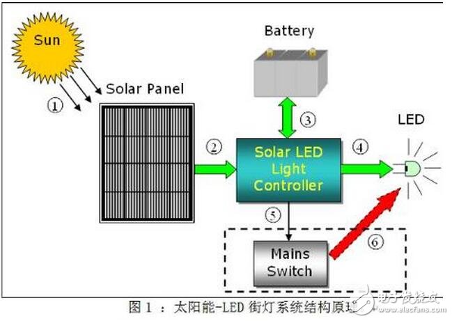
Figure 1 is a schematic diagram of the structure of a solar-LED Street Light. When the solar panel is illuminated by sunlight, its internal PN junction will form a new pair of electrons and holes, and a DC current will be generated in one loop; this current will flow into the controller and will charge the battery in some way. The battery will be charged during the day and energy will be supplied to the LED at night. The operation of the LED is performed by the controller. While ensuring the constant current operation of the LED, the controller also monitors the status of the LED and controls the working time. In the case of continuous rainy days and insufficient battery power, the controller will send a control signal to activate the external mains supply system (not included in the controller) to ensure the normal operation of the LED. The external mains supply system is only used as a backup energy source and will only be used if the battery is not fully charged. Charging the battery is done entirely by solar energy to ensure maximum use of solar energy.
When the solar panel comes in, it will first be connected to the DC/DC converter (battery charging circuit) through a switch MOS tube KCHG. The output of this converter is connected to the two ends of the battery (the actual circuit will be connected to the battery through a fuse first). ). In addition, KCHG has two functions: one is to prevent the reverse charging flow from the battery when the output of the solar cell is low; the other is to protect the circuit when the polarity of the solar panel is reversed. The DC/DC converter adopts a buck topology, and the topology selection must consider not only the maximum power point voltage of the solar panel and the maximum voltage of the battery, but also the efficiency and cost. The battery and the LED are also connected through a DC/DC converter (LED drive circuit). The LED is controlled by constant current. Considering the fluctuation range of the battery voltage and the operating voltage range of the LED, the flyback topology is used in the design circuit. Structure to ensure constant current output. The efficiency of the flyback topology is generally not as simple as the boost or step-down circuit. If you want to improve the efficiency of the system, you can use the boost or step-down circuit by optimizing the relationship between the battery voltage and the LED voltage to improve efficiency and possibly further reduce cost.
The control of the whole controller is realized by an MCU. The main work of the MCU includes the following points: First, the MPPT algorithm is used to optimize the working efficiency of the solar panel; second, the appropriate charging mode is adopted for different states of the battery; The constant current output of the drive circuit; the fourth is to judge the day and night to switch the battery charging and discharging mode; the last is to provide monitoring protection, temperature monitoring, status output and user control input detection (DIP1~4). The choice of MCU is mainly to meet the needs of ADC, GPIO and external interrupts, and does not need to pursue speed alone. Table 1 lists the use of MCU peripherals in the actual circuit. Considering the need for future expansion, the main control chip uses ST M32F101RXT6 (the latest ST M32 series MCU from STMicroelectronics, using the Cortex-M3 core).
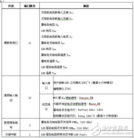
Table 1: MCU Peripheral Assignments.
The controller auxiliary power supply is directly changed from the battery. The battery input is 12V through the linear power supply (L78L12), and the logic circuit and PWM switch signal are amplified. 3.3V is connected to the switching power supply (L5970D) through 12V, mainly for the MCU and peripheral circuits. For power supply, the reason why the switching power supply is used is to improve the conversion efficiency (reduce the battery power consumption) and to provide sufficient load when expanding the system in the future. Of course, in order to reduce the cost, it can be realized by a linear power supply.
Controller main function
The main functions of the controller include two aspects: battery charging and battery powering the LED.
1. Battery charging
When the system detects sufficient ambient light, the controller enters charging mode. There are two important voltage values for battery charging: deep discharge voltage and float charge voltage. The former represents the state in which the battery power is used up under normal use, while the latter represents the highest limit voltage for battery charging. These parameters should be found in the battery product manual. In the design circuit, for the 12V battery, set the deep discharge voltage to 11V and the float charge voltage to 13.8V (both voltage values at room temperature, the two values in the software increase the corresponding temperature compensation), specific charging The mode is shown in Table 2.
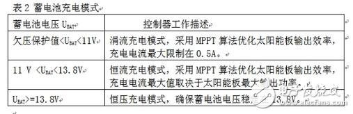
Table 2: Battery Charging Mode
It can be seen from Table 2 that the trickle charge mode and the constant current charge mode will use the MPPT algorithm. There are many ways to implement the MPPT algorithm. There are many papers in the industry to discuss this. In general, each has excellent Inferior, the design circuit uses a relatively simple perturbation observation method (Perturbance and Observaon). The basic idea of this control method is to increase or decrease the duty cycle by increasing or decreasing the PWMCHG duty cycle of the charging circuit switching signal and then observing whether the output power is getting larger or smaller. Since the output of the solar panel changes relatively slowly and is a single pole, this method can still receive better results.
2. Battery discharge
When the system detects that the ambient light is insufficient, it will enter the battery to supply power to the LED. The LED current is sampled back to the MCU through the high current sense detection chip (TSC101AILT), and the MCU obtains a constant output current by adjusting the duty cycle of the switching signal PWMDRV. In order to achieve energy saving, the constant current value of the LED is adjusted according to the ambient light intensity detected by the system: when the ambient light is dimmed from light to dark, the output current of the system will be correspondingly small to large; when the ambient light is completely dark, The output current of the system also reaches the preset maximum value. In addition to controlling the output of the LED by ambient light, the user can also turn on the time control function by setting the state of the switches DIP1~4. The system will control the LEDs from 5 minutes to 12 hours according to the setting combination of DIP1~4.
In addition, in order to improve the reliability of the system, the design circuit adds protection functions for a series of hardware and software such as solar panels, batteries and LEDs. Based on this system platform, system performance can be further optimized from the aspects of adding intelligent LED operation mode, adding communication modules and adopting wind and solar complementary systems.
Conclusion of this paper
Solar-LED streetlights not only provide clean lighting, but also efficient and environmentally friendly LEDs to illuminate roads, while at the same time reducing greenhouse gas emissions and achieving green lighting. The streetlight system has been successfully implemented at the entrance of the STMicroelectronics building. All streetlight systems have been in operation for half a year and work normally. As the price of solar panels is further reduced and the cost performance of LEDs is increasing, it is believed that this system will be more and more widely used.
The above is the Solar Street Light Design for STM32MCU we have listed for you. You can submit the following form to obtain more industry information we provide for you.
You can visit our website or contact us, and we will provide the latest consultation and solutions
Send Inquiry
Most Popular
lastest New
Send Inquiry
Privacy statement: Your privacy is very important to Us. Our company promises not to disclose your personal information to any external company with out your explicit permission.
Fill in more information so that we can get in touch with you faster
Privacy statement: Your privacy is very important to Us. Our company promises not to disclose your personal information to any external company with out your explicit permission.